

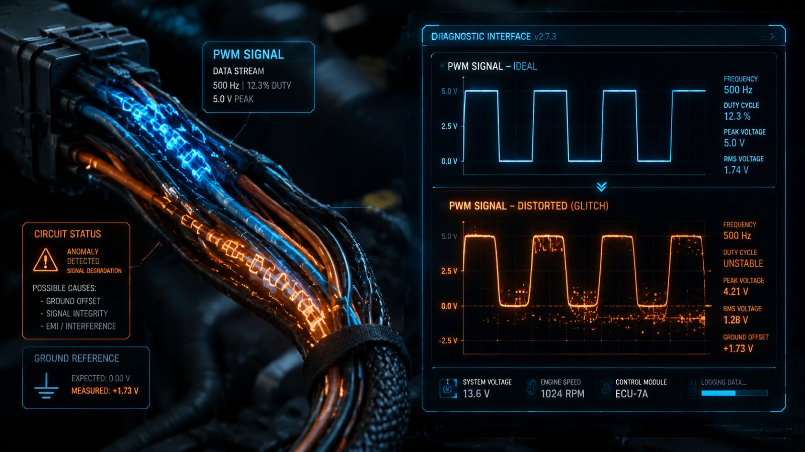
Modern automotive climate controls rely on precise pulse-width modulation signals to regulate cooling performance on long highway trips. When standard scanners fail to detect intermittent electrical dropouts under high thermal loads, Gregg Smith Automotive deploys advanced multi-channel digital oscilloscopes to intercept and correct distorted control waves along the US-27 corridor.
Florida drivers assume AC failure is a straightforward mechanical issue. However, vehicles blowing cold around town but failing on US-27 highway hauls are suffering from high-frequency digital communication loop drops. When these microscopic glitches occur, standard service gauges and serial scan tools become completely useless at diagnosing the underlying root failure.
Beyond Serial Scanner Data and the Square Wave Reality of Modern Cars
Relying on basic serial scan tools often leads to misdiagnosing complex automotive electrical failures. Because these tools process data in slow mathematical averages rather than real-time wave captures, they fail to catch rapid, high-frequency circuit dropouts. To fix an intermittent cooling issue under load, a technician must look past simple code readers and monitor the active circuit directly.
- Standard scanners only poll system data every few seconds, causing them to completely miss brief millisecond signal drops.
- The absence of stored trouble codes does not guarantee your climate control electronics are operating correctly.
- Diagnosing modern pulse-modulated systems requires physically tapping the circuit to read live electrical waves in real time.
The Physics of Pulse Width Modulation in Compressors and Fans
Modern climate control modules do not regulate heavy electrical loads like variable-displacement compressor solenoids or brushless condenser fan assemblies by stepping down traditional system voltage, as lowering static voltage would generate immense heat and destroy the controller. Instead, automotive computers utilize a digital control language called Pulse-Width Modulation (PWM). The system delivers a continuous, full 14-volt signal to the component while cycling the electrical grounding path on and off hundreds of times per second to vary speed and capacity.
- The Duty Cycle Percentage: Component speed is determined by the ratio of active “on” time relative to the total length of the cycle wave, meaning longer ground connection times translate to higher operating speeds.
- The High-Speed Switch: This rapid, micro-second cycling is handled safely by high-capacity solid-state switching transistors known as Insulated-Gate Bipolar Transistors (IGBTs) mounted inside the vehicle’s control modules.
- The Square Wave Blueprint: When viewed on a high-speed diagnostic oscilloscope, a healthy, clean PWM control signal renders as a perfectly sharp square wave with precise vertical edges and corners.
Sustaining Precision Temperatures Along the Blistering US 27 Corridor
During highway travel on the US-27 corridor, extreme heat places immense thermodynamic stress on your vehicle’s cooling system, requiring high-duty-cycle signals to manage fan performance. This intense demand creates significant electrical loads on internal control transistors, which our technicians analyze using oscilloscopes to identify specific signal markers of impending failure.
Automotive Climate Control Waveform Diagnostic Profiles
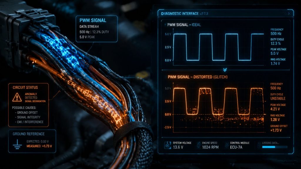
| Electronic Signal Evaluation Marker | Healthy Factory PWM Control Waveform | Corrupted Intermittent Control Waveform |
| Visual Wave Profile Structure | Razor-sharp vertical square edges | Rounded corners or slanted vertical drops |
| Ground Circuit Potential | Drops cleanly and fully down to 0.0 Volts | Floats out of spec at 1.5 Volts or higher |
| Duty Cycle Under High Thermal Load | Sustains solid, continuous 85% execution | Spikes wildly or drops out to 0% completely |
| Physical Hardware Response | Cooling fan motor runs at full velocity | Component stalls or shuts down under load |
Thermal fatigue in a controller transistor may not be apparent during short or cool drives. However, prolonged highway travel generates intense underhood heat that spikes internal resistance. This causes the control wave’s sharp square edges to collapse, preventing the cooling fan from maintaining its necessary speed.
Catching Waveform Glitches Before They Destroy Your Hardware
When an underhood fan controller or a PWM variable-displacement solenoid drops its signal on the highway, high-side refrigerant pressures spike drastically. To prevent a catastrophic line blowout, the vehicle’s automated safety software instantly cuts power to the compressor clutch. Un-certified shops often misdiagnose this protective shutdown as a mechanical hardware failure, replacing perfectly good compressors that will simply fail again the moment you resume your hot US-27 commute and re-trigger the underlying electrical signal distortion.
Gregg Smith Automotive uses ultra-fine back-probe pins to safely intercept active signals without damaging insulation. By connecting a multi-channel digital storage oscilloscope during high thermal load simulations, we monitor control wave behavior in real time. Detecting rounded vertical drops or floating ground potentials allows us to isolate specific failing modules or pins, preventing the unnecessary replacement of functional mechanical components.
Understanding the Value of Precise Signal Evaluation
Modern automotive climate control systems are sophisticated electronic networks, not simple mechanical loops. If your vehicle cools effectively around town but drops its cooling capacity during extended highway driving, you are likely dealing with an advanced digital signal tracking failure rather than a physical part breakdown. Resolving these fleeting underhood glitches requires a facility that treats vehicle telematics with laboratory-level discipline instead of speculative parts replacement.
- Advanced Signal Tracing: Intermittent cooling drops during long hauls point to a failure in high-frequency digital communication streams.
- Laboratory Precision: Finding micro-second glitches requires high-speed multi-channel digital oscilloscopes and deep pulse-width modulation expertise.
- Data-Driven Care: Prioritizing live visual waveform data over trial-and-error guesswork protects your budget and ensures long-term vehicle reliability.
Secure Specialized Electrical Diagnostics Over Costly Guesswork
Don’t let an elusive electrical glitch trick you into replacing expensive components that are mechanically perfect. Our certified master technicians at Gregg Smith Automotive possess the high-speed multi-channel lab scopes, back-probing equipment, and advanced wave-analysis training required to isolate and fix your vehicle’s underlying wiring anomalies cleanly and accurately.
Restore continuous climate control stability and request your advanced signal check today.
- Visit the Diagnostic Lab: 6202 SE Abshier Blvd, Belleview, FL 34420
- Call the Bay Directly: (352) 245-6738
- Request Your Oscilloscope Evaluation: GreggSmithAutomotive.com
Frequently Asked Questions
Why does my vehicle’s air conditioning work fine around town but turn warm on long highway hauls?
This occurs when parts like the cooling fan module or compressor solenoid suffer thermal expansion or electrical breakdown under high highway loads. Heat-induced resistance in worn internal components distorts the control signal, causing the computer to disable cooling.
What is the advantage of using an oscilloscope over a standard digital multimeter?
Digital multimeters are too slow for high-frequency digital glitches. They sample circuits only a few times per second, providing averaged voltage readings. Consequently, if a pulse-width modulation line switches rapidly, the multimeter displays a generic average voltage that hides critical signal dropouts or microscopic voltage drops.
Can a faulty ground wire distort a pulse width modulation square wave?
Yes. Since pulse-width modulation often uses ground-side switching, poor ground points with high resistance prevent circuit voltage from hitting zero. This “voltage float” distorts the square wave and deprives components of necessary current.
What happens if a variable displacement compressor solenoid receives a corrupted signal?
Variable-displacement compressors use internal electronic solenoid valves to adjust swashplate angles, regulating refrigerant flow based on cooling needs. If electrical noise or rounded edges distort the incoming PWM control wave, the solenoid cannot accurately position the swashplate. This distortion leads to unstable line pressures and insufficient cooling.
Is it safe for a technician to probe into my vehicle’s factory wiring harness during a scope test?
Yes, using professional tooling. Our technicians use specialized, ultra-thin back-probe pins that slide along connector weather seals. This ensures solid electrical contact with terminal pins without puncturing or damaging the vehicle’s protective wiring jackets.